The valve controls and conveys the medium by the cooperation between the valve body and the valve disc. After the valve is closed, the pressure at the inlet end and the outlet end is different, and a pressure difference is generated. When the valve is opened, the existence of the pressure difference causes the media to have a huge instantaneous impact on the valve components and piping, causing the valve to vibrate with noise when the media pass through the valve. Vibration affects the sealing performance and service life of the valve and pipeline connected to it, and other equipment used for inspection. In some specific high-pressure working conditions, especially those applied to high-pressure pipeline systems, the vibration is particularly intense, which cannot meet the requirements of stable operation, small vibration amplitude and low noise.

Valve buffer structure for reducing valve opening and closing vibration and noise
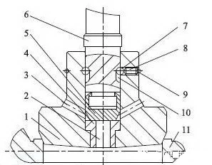
The valve buffer structure is a structure consisting of a central through hole and two symmetrically disposed bypass holes (not limited to two) set on the valve disc that matches the valve body, and the bypass hole is in connection with the central through hole. A sealing seat is arranged from the valve sealing end face to the central through-hole section at the bypass hole, and the sealing seat is provided with a sealing flap to form a sealing assembly. When the sealing assembly is in the closed state, the bypass hole and the lower central through hole are not in communication with each, and when the sealing assembly is in the open state, the bypass hole communicates with the lower central through hole to connect the inlet and the outlet end of the valve. The sealing flap is connected to one end of the transmission bar, and the other end of the transmission bar protrudes from the central through hole and is connected with the driving mechanism. The height of the limiting groove is the distance that the sealing flap moves in the through hole of the center of the valve disc. The central through hole in the lower part of the valve disc should be communicated with the bypass hole after the sealing assembly is opened.
When the valve is opened, the transmission rod is raised by the driving mechanism, and the sealing flap connected thereto rises accordingly. At this time, the valve disc does not move, the sealing assembly is first opened, and the medium passes through the central through hole and the bypass hole from the inlet end of the valve to the outlet end of the valve, balancing the pressure at the inlet and outlet of the valve with a small amount of incoming media. As the driving rod continues to rise, under the restriction of the position-limit mechanism, the sealing flap and the valve disc move upwards at the same time, and the valve opens. Conversely, when the driving rod moves downwards, the seal assembly is closed first, and as the driving rod continues to move downwards, the valve is closed.
The valve buffer structure reduces the vibration and noise by adjusting the inlet and outlet pressures of the valve to ensure the valve working performance. The valve disc is provided with a central through hole and a bypass hole communicating with the central through hole. A sealing assembly is arranged between the central through hole and the bypass hole, and the sealing flap of the sealing assembly is connected with the transmission bar, and there is a position limit mechanism between the transmission rod and the valve disc. The valve disc wall is provided with a through hole, and a limiting slot is arranged at a position opposite to the through hole on the transmission rod. The limiting ball is located in the through hole and the limiting slot, and the limiting bolt is arranged in the through hole to limit the movement of the limiting ball.
The buffer structure is arranged on the valve disc, which reduces the pressure difference between the inlet and the outlet of the valve, realizes the pressure balance, and alleviates the impact of the medium on the valve. The valve buffer structure is suitable for high-pressure pipeline system. The valve opening and closing operation is stable, the vibration amplitude is small, the noise is low, and the service life of the components is extended, hence the valve buffer structure meets the valve working conditions well.

