High-quality seamless steel pipes are extensively used in aerospace, military, nuclear power, and other industries, which impose increasingly stringent demands on non-destructive testing techniques, requiring ultrasonic scanning of the entire pipe body. Traditional automatic ultrasonic testing equipment for seamless steel pipes primarily uses multi-channel array probe technology to enhance detection efficiency. However, because the probe size exceeds the sound beam width, it does not achieve complete coverage of the pipe body. This paper introduces phased array ultrasonic technology using full circumferential cylindrical and axial arrays, examines a single-pass comprehensive scanning method for arbitrary oblique defects, and develops various types of automated phased array ultrasonic equipment for tubes and rods to achieve complete coverage of the pipe body, thereby enhancing detection capabilities and reliability.
1. Introduction
Steel pipe production plays a crucial role in the national economy, leading nations worldwide to prioritize advancements in its manufacturing technology. Seamless steel pipes are primarily utilized in high-temperature, high-pressure, and corrosion-resistant environments, as well as in critical industrial sectors. While some conveying pipelines and structural pipes have been partially replaced by welded pipes, the production of seamless steel pipes is expected to accelerate with the increased adoption of cost-effective continuous casting billets. As industries demand enhanced quality, diversity, and efficiency in seamless steel pipes, contemporary technological advancements have been integrated into multiple stages of steel pipe production. The production processes of seamless steel pipes can lead to defects such as straight lines, cracks, transverse cracks, and delamination. Ultrasonic testing is particularly effective in detecting these defects. It can well control the quality level of seamless steel pipes. Seamless steel pipes are particularly suitable for the implementation of ultrasonic flaw detection automation due to their regular appearance. Ultrasonic testing effectively ensures the quality of seamless steel pipes. The consistent geometry of seamless steel pipes makes them ideal candidates for automated ultrasonic flaw detection. Owing to its high reliability and advanced capabilities, non-destructive testing has increasingly replaced water pressure testing.
2. Methodology
2.1 Basic Principles
Phased array technology, currently the most prevalent ultrasonic testing method, offers several key advantages: high beam density, rapid and straightforward defect waveform recognition, dynamic depth focusing, electronic beam angle adjustment, operational convenience, and the simultaneous generation of multiple beams with varying angles and focal lengths. Phased array technology is extensively utilized. Employing phased array technology in ultrasonic testing of seamless steel pipes significantly reduces system calibration time and enhances the signal-to-noise ratio. Multi-beam multiplexing technology simplifies machinery complexity without altering equipment functionality. Phased array technology effectively detects delamination and transverse defects often overlooked by conventional A-scan ultrasound. Additionally, phased array technology utilizing axial arrays allows longitudinal probes to effectively detect oblique defects. Phased array systems employing full-circle cylindrical arrays can perform C-scan imaging without the need for external circumferential encoders. Phased array flaw detection in seamless steel pipes employs line scanning, where beams generated by array elements with varying activation sequences at a fixed emission angle collectively create an image. The scanning point progresses linearly, producing a parallelogram-shaped image at a specified beam angle. Figure 1 illustrates the schematic diagram of the line scanning process.
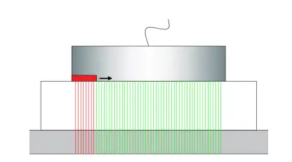
Figure 1 Line scanning
Line scanning has the following characteristics:
1) Phased array line scanning enables beam steering at specified angles, facilitating extensive area inspections at consistent angles and effectively detecting both longitudinal and transverse flaws.
2) Phased array line scanning without angle is suitable for layered detection.
3) The coverage area does not need to move the probe to achieve full detection of the target area.
2.2 System Description
2.2.1 System Overview
This paper presents phased array ultrasonic testing (PAUT) for inspecting seamless steel pipes. For large-diameter pipes, PAUT utilizing axial arrays is typically employed. In contrast, small-diameter pipes are inspected using PAUT with full circumferential cylindrical arrays. Axial phased array technology typically encompasses functions such as longitudinal (oblique) and transverse flaw detection, as well as thickness measurement. A one-dimensional linear phased array probe is chosen, with its active elements aligned along the longitudinal axis of the steel pipe under inspection. Longitudinal detection utilizes a fixed beam angle, with the ultrasonic beam electronically scanned linearly along the probe's active axis. Oblique detection builds upon the longitudinal probe by employing phased array technology to electronically steer the beam along the active axis, in conjunction with the probe's physical angle, to generate the desired oblique beam. The oblique angle is electronically controlled, as illustrated in Figure 2. The oblique angle detection range spans up to 45°. To effectively detect defects with larger inclination angles, the probe's element pitch should be minimized, ideally less than half the wavelength of the emitted ultrasound. It is recommended to set the angular increment for inclination angle scanning at 2.5°. Phased array ultrasound enables simultaneous detection of defects across multiple inclination angles; however, increasing the number of simultaneously detected angles can reduce the overall flaw detection speed. Figure 3 illustrates the schematic diagram of longitudinal and oblique detection configurations.
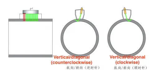
Figure 2 Phased array longitudinal/oblique probe layout
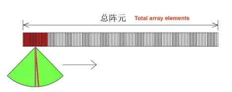
Figure 3 Schematic diagram of longitudinal/oblique detection
In transverse detection, the phased array probe is positioned perpendicular to the steel pipe's surface, with its active elements aligned along the pipe's longitudinal axis. The phased array instrument simultaneously generates dual focusing laws to produce forward and backward shear wave beams (typically 45°-70°), enabling bidirectional inspection for comprehensive transverse defect detection. To enable effective electronic beam steering, the phased array probe must use small-element pitch and moderate frequency, as illustrated in Figure 4.
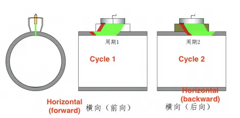
Figure 4 The transverse detection
For layered thickness measurements, the phased array probe is oriented normal to the pipe surface with its active axis aligned parallel to the pipe's longitudinal axis. The phased array instrument concurrently generates dual focusing laws - including 0° longitudinal wave beams optimized for layer resolution and thickness gauging. For enhanced longitudinal resolution in layer/thickness measurements, a moderately higher probe frequency is recommended, as illustrated in Figure 5.
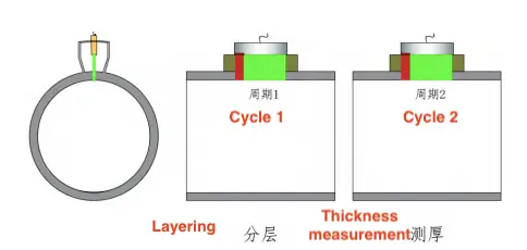
Figure 5 Layering/Thickness measurement
This method applies to flaw detection scenarios where the steel pipe either rotates in place with the probe moving along its axis or advances in a spiral while the probe remains stationary. To prevent missing defects, the probe's movement speed should synchronize with the steel pipe's rotation, ensuring that the probe advances less than 85% of its effective beam width per rotation.
In full-circumference cylindrical array phased array technology, a one-dimensional linear array cylindrical probe is employed, with its active axis aligned along the circumference of the steel pipe under inspection. This configuration enables comprehensive detection capabilities, including longitudinal, layered, thickness measurements, and transverse flaw detection. Longitudinal 1 layered/thickness measurement detection does not rely on the physical deflection angle, but uses an electronic sound beam to deflect on the circumference and cooperate with the linear scanning movement on the active axis for detection. Four focusing laws are employed: clockwise and counterclockwise shear wave oblique sound beams for bidirectional detection of longitudinal defects, and two 0° longitudinal wave sound beams for layering and wall thickness measurements. The principle is illustrated in Figure 6.
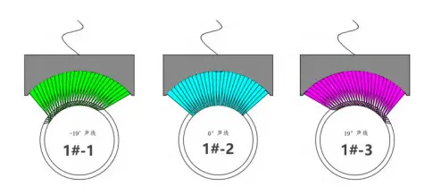
Figure 6 The focusing law of full-circle cylindrical array phased array detection
The full-circumference phased array system utilizes cylindrical probe arrays surrounding the pipe to achieve complete ultrasonic inspection during linear pipe traversal. The system accommodates varying pipe diameters by adjusting the number of cylindrical probes to ensure full circumferential coverage. Probe arrays are arranged with specified wafer overlap between adjacent units, as illustrated in Figure 7.
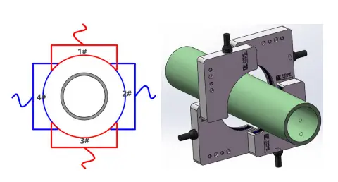
Figure 7: Schematic Diagram of Longitudinal, Layered, and Thickness Probe Coverage
In transverse detection, the phased array probe utilizes physical deflection angles for flaw detection, with the electronic sound beam moving linearly along the probe's active axis. The probe's wafer layout is conical in shape, as depicted in Figure 8.
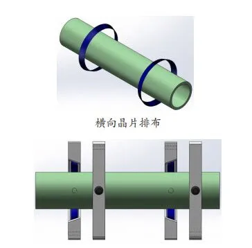
Figure 8 Transverse probe coverage
Phased array technology enables comprehensive detection of both longitudinal and transverse defects through the use of a compact one-dimensional linear phased array probe combined with fan-shaped scanning. For detecting oblique defects ranging from 0° to 60°, a single probe is employed with its active axis aligned parallel to the steel pipe's axis. The probe is physically inclined to direct acoustic waves onto the pipe's surface. Utilizing fan-shaped scanning focusing laws, the resolution is typically set to 0.5°, and the scanning range spans from -30° to 30°, effectively identifying all oblique defects within this angular range. This approach is also compatible with longitudinal defect detection. By configuring two probes for clockwise and counterclockwise incidence, bidirectional oblique defect detection is achieved, as illustrated in Figure 9(a).
For oblique defects between 45° and 90°, a single probe is used with its active axis perpendicular to the steel pipe's axis. The probe's physical inclination angle facilitates effective insonification of the pipe. Applying fan-shaped scanning focusing laws with a resolution of 0.5° and a scanning range from -30° to 30° allows for the detection of all oblique defects within this sector. This method is suitable for transverse defect detection as well. Implementing two probes for forward and backward incidence enables bidirectional oblique defect detection, depicted in Figure 9(b). Employing probes set at 0°–60° and 45°–90° orientations allows for the detection of oblique defects at any angle within the 0°–90° range.
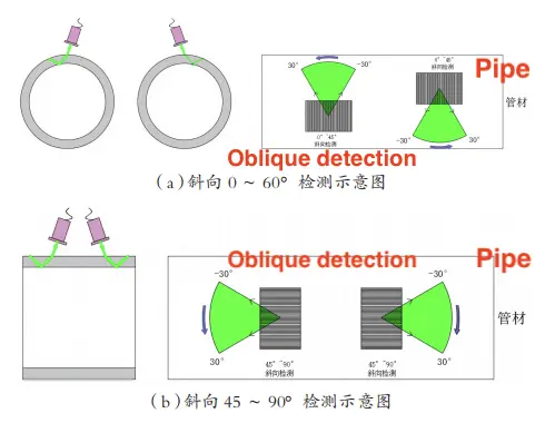
(a) Detection from 0 to 60° in the clockwise direction (b) Detection from 45 to 90° in the oblique direction
Figure 9 The oblique detection
3. Experimental Results
3.1 Simulated Defect Arrangement
To evaluate the detection capabilities, artificial defects were introduced into seamless steel pipes with the following specifications: 356 mm × 20 mm, 38 mm × 0.5 mm, and 60 mm × 15 mm. These defects were designed to emulate those found in actual seamless steel pipes, with dimensions determined based on industry standards.
The defects were categorized and detailed as follows:
Defect 1: Longitudinal groove on the outer wall, measuring 25 mm in length, 1.0 mm in depth, and 0.3 mm in width.
Defect 2: Transverse groove on the inner wall, measuring 25 mm in length, 1.0 mm in depth, and 0.3 mm in width.
Defect 3: Longitudinal groove on the inner wall, measuring 25 mm in length, 1.0 mm in depth, and 0.3 mm in width.
Defect 4: Transverse groove on the outer wall, measuring 25 mm in length, 1.0 mm in depth, and 0.3 mm in width.
Defect 5: Flat bottom hole with a diameter of 6 mm and a depth of 10 mm.
Each defect was positioned 200 mm from its respective end.

Figure 10: Defect Distribution Diagram of the 356 mm × 20 mm Sample Pipe
Defect Descriptions:
Defect 1: Longitudinal notch on the outer wall, measuring 10 mm in length, 0.1 mm in depth, and 0.2 mm in width.
Defect 2: Transverse notch on the inner wall, measuring 10 mm in length, 0.1 mm in depth, and 0.2 mm in width.
Defect 3: Longitudinal notch on the inner wall, measuring 10 mm in length, 0.1 mm in depth, and 0.2 mm in width.
Defect 4: Transverse notch on the outer wall, measuring 10 mm in length, 0.1 mm in depth, and 0.2 mm in width.
Defect 5: Flat-bottom hole with a diameter of 6 mm and a depth of 10 mm.
Defect Placement:
Defects 1 through 4 are positioned 50 mm from their respective ends.
Defects 5 and 6 are centrally located along the length of the steel pipe.

Figure 11: Defect Distribution Diagram for the 38 mm × 0.5 mm Sample Pipe
Defect 1: Transverse groove on the outer wall, measuring 25 mm in length, 0.75 mm in depth, and 0.3 mm in width.
Defect 2: Outer wall groove oriented at a 10° angle to the pipe axis, measuring 25 mm in length, 0.75 mm in depth, and 0.3 mm in width.
Defect 3: Outer wall groove oriented at a 20° angle to the pipe axis, measuring 25 mm in length, 0.75 mm in depth, and 0.3 mm in width.
Defect 4: Outer wall groove oriented at a 30° angle to the pipe axis, measuring 25 mm in length, 0.75 mm in depth, and 0.3 mm in width.
Defect 5: Outer wall groove oriented at a 40° angle to the pipe axis, measuring 25 mm in length, 0.75 mm in depth, and 0.3 mm in width.
Defect 6: Outer wall groove oriented at a 50° angle to the pipe axis, measuring 25 mm in length, 0.75 mm in depth, and 0.3 mm in width.
Defect 7: Outer wall groove oriented at a 60° angle to the pipe axis, measuring 25 mm in length, 0.75 mm in depth, and 0.3 mm in width.
Defect 8: Outer wall groove oriented at a 70° angle to the pipe axis, measuring 25 mm in length, 0.75 mm in depth, and 0.3 mm in width.
Defect 9: Longitudinal groove on the outer wall, measuring 25 mm in length, 0.75 mm in depth, and 0.3 mm in width.
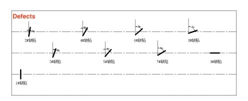
Figure 12: Defect Distribution for the 60 mm × 15 mm Sample Tube
3.2 Test results
Sample tube 356x20mm Used to test the phased array technology based on the axial array, and the detection results are shown in Figure 13.The sample tube 38x0.5mm is used to test the full circumferential cylindrical array phased array technology, and the detection results are shown in Figure 14. The 60×15 mm sample tube was utilized to evaluate phased array detection technology for comprehensive oblique defects, including both longitudinal and transverse types; the detection results are presented in Figure 15.
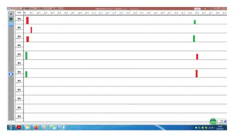
Figure 13: Phased array test results for the 356×20 mm sample tube
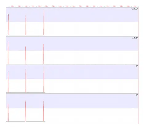
Figure 14: Phased array test results for the 38×0.5 mm sample tube
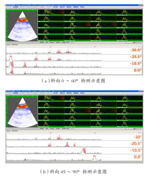
(a) Detection diagram for 0–60° (b) Detection diagram for 45–90°
Figure 15: Phased array test results for the 60×15 mm sample tube
The aforementioned tests were meticulously coordinated, aligning the probe's effective beam width, pitch, and the steel pipe's transmission and rotation speeds. Each test was conducted multiple times to statistically analyze the occurrence of false alarms.
They can meet the requirements of YB/T4082-2011 "Comprehensive Performance Test Method of Steel Pipe Automatic Ultrasonic Flaw Detection System". At the same time, the artificial defects are engraved according to GB/T 5777-2008 "Ultrasonic Flaw Detection Method for Seamless Steel Pipes" standard, and the signal-to-noise ratio can reach more than 10dB. It can meet the needs of automated ultrasonic testing.
4. Conclusion
The system complies with the YB/T 4082-2011 standard, "Comprehensive Performance Test Method of Steel Pipe Automatic Ultrasonic Flaw Detection System." Artificial defects are introduced in accordance with the GB/T 5777-2008 standard, "Ultrasonic Flaw Detection Method for Seamless Steel Pipes," achieving a signal-to-noise ratio exceeding 10 dB, thereby fulfilling the requirements for automated ultrasonic testing. Implementing phased array technology simplifies user operation, enhances system performance, decreases the likelihood of missed detections, and improves product quality.