304 stainless steel has high strength, excellent low-temperature toughness and good weldability at-196℃, and is often used in low-temperature service pipelines of LNG core process modules. A project design requires that a part of 304 stainless steel pipes be welded by GMAW (Metal Arc Welding) process, and some limited requirements are put forward for several elements of the welding process. In the early stage of the project, welding tests were conducted and various properties of welded joints were tested. As a result, there were many problems of insufficient fusion which could not be detected by conventional X-ray, and the root cracking of welded joints appeared in different degrees in side bending and intergranular corrosion tests. Therefore, the reasons that may lead to insufficient fusion are analyzed and verified by several groups of welding tests. The results show that the performance of the optimized welded joint meets the relevant requirements specified in the standard, which further verifies that the optimized welding process is appropriate. According to the design requirements of the project, a part of the 304 stainless steel pipe systems is welded by the GMAW process, with the applicable nominal diameter of 500~2750mm and wall thickness of 5.5 - 40 mm. This involves the prefabrication and on-site installation of pipelines in the workshop, and the welding of pipe fittings such as pipelines and flanges, tees and bends. Specific requirements for welding are as follows:
1) GMAW-S (Metal Arc Welding) process is adopted for root welding, and the corresponding welding equipment is selected from several internationally renowned brands.
2) GMAW-P (Metal Arc Welding Pulse Transition Arc Welding) process is adopted for hot welding, and the welding equipment is the same as that for root welding. The welding methods and equipment for other filling and cover surfaces are not limited.
3) The welding material is ER308L solid-core welding wire, which has certain requirements for the silicon content in the welding wire, that is, the silicon content should be slightly higher than that of the traditional welding wire.
4) The welding shielding gas is 98% argon +2%CO2, and the back shielding gas is pure argon.
5) Welding procedure qualification shall comply with the relevant requirements of ASME B31.3 and ASME IX, and intergranular corrosion test of welded joints shall be carried out according to ASTM A262 PracticeE method.
Pre-welding test
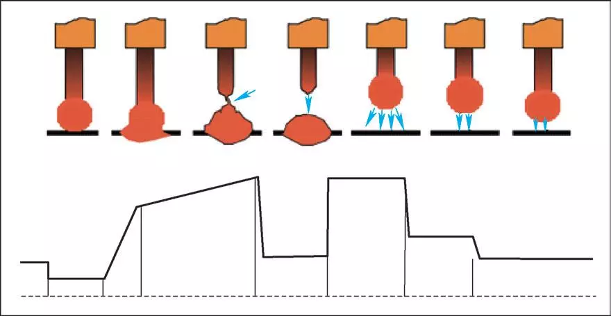
After combing and implementing all aspects of the welding process, the suitable GMAW welder and ER308L welding wire were selected to carry out the preliminary welding test. GMAW-S process is suitable for stainless steel root welding. Its current output and unique waveform control technology are more suitable for root welding. The root fusion is full and uniform, the welding spatter is small, the welding efficiency is high, and the heat input is small. Its output characteristics are shown in Figure 1. After a week's trial welding, the welding technicians have initially adapted to GMAW-S and GMAW-P processes for welding 304 stainless steel, and the welding operation and weld formation tend to be stable. Therefore, they are ready to change from trial welding to research and testing welding parameters and physical and chemical properties of welded joints.

A) GMAW-s waveform control

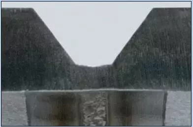
B) welding forming of root welding
Figure 1 output characteristics of GMAW-S root welding
Test material
304 stainless steel pipe with φ 355.6mm and a wall thickness of 11mm was selected as the base material, and ER308L with φ 1.0mm was selected as the welding wire. The welding position is 5G. Steel pipes of this size are selected for welding, and 4 layers need to be welded: the GMAW-S process is adopted for root welding, the GMAW-P process is adopted for hot welding and filling, and the GMAW-P process is adopted for the cover surface. Under the condition of a low workload, the following aspects can be comprehensively investigated: output characteristics of welding methods, welding operation in all positions, weld bead fusion and forming, etc.
Groove form
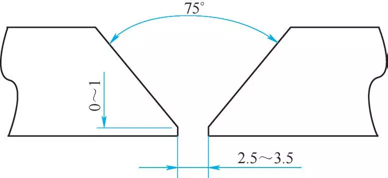
The groove adopts the single-sided 75 recommended by the ASME B31.3 standard, as shown in Figure 2. Because the GMAW-S process is semi-automatic wire feeding, the welding speed is fast and the welding heat input is small, so the blunt edge of the groove is almost 0 mm. Only before assembling the groove, grind the root with a grinder to remove the burrs that may remain after cutting the root. The gap of the pair is 2.5 - 3.5 mm. According to the feedback from the welding technician, this gap range is the easiest for all-position welding forming operations.

Figure 2 Form of test groove
Welding parameter
In the actual welding process, two specimens were welded, and the average values of welding parameters are shown in Table 1. Under this parameter, the weld bead of the specimen is good in appearance, and the weld formation is symmetrical. The appearance formation of both sides of the weld bead meets the appearance requirements of ASME standard, and it has passed the appearance inspection of engineers and inspectors.
Table 1 Welding parameters selected in the welding test
Nondestructive examination
Magnetic particle and X-ray inspection shall be carried out on welded specimens, and ASME VIII standards shall be applied for magnetic particle inspection, and ASMEB31.3 standards shall be applied for X-ray inspection and judgment. The results of non-destructive testing all meet the relevant requirements of the standard and are judged as qualified.
Physical and chemical property test
According to the relevant requirements of the ASME IX standard, the mechanical properties of welded joints were tested. Four side bending specimens, two reduced cross-section tensile specimens, three groups of low-temperature impact specimens and two macroscopic specimens were selected, and the ferrite content of welded joints was determined [1]. In addition, three intergranular corrosion specimens were taken and the welded joints were tested according to the ASTM A262 Practice E method.
After the test, the root crack appeared in the side bending specimen, and the root crack also appeared in the root bending test after intergranular corrosion, which indicated that there was a problem in the root fusion of the welded specimen. Although no over-standard defects were found in NDT, it is highly suspected that the root cold lap problem occurred. A cold lap joint is a non-standard welding defect term used by AWS technology and standard documents when describing a defect in GMAW welded joints. The so-called cold lap, in fact, is not fused, which often easily occurs in GMAW welds. A cold lap joint is different from the unfused joint in a general sense, which is characterized by small defect size, and it is not easy to be detected by common methods such as visual inspection and RT. The results show that the causes of the cold lap are splashing on the feet of both sides of the molten pool, overflow of the molten pool and the combination of the above two, and the size of the cold lap is 0.01 ~ 1.5 mm. Among them, the large cold lap joint is easy to be visually observed, while the 10μm cold lap joint is difficult to be found by nondestructive testing.
Cause analysis and optimization measures of cracking
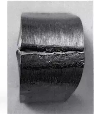
Because there are cracks in almost all the circumferential positions of the pipe, and in the adjacent positions of the bent cracked specimens, the bent specimens with supplementary sampling also have different degrees of cracking problems. At first, it is considered that the main reason for poor root fusion is that the welding parameters are small and the heat input is insufficient, so the adjustment direction is to appropriately increase the welding parameters, mainly to increase the wire feeding speed and welding current, which are positively correlated. However, through the trial welding, the bending cracking problem similar to that in Figure 3 still occurs. Therefore, it is agreed that the method of increasing wire feeding speed and welding current is not the main direction of adjustment, because the welding parameters adopted by technicians at present are more appropriate to control in the welding process. If the parameters are increased too much, there will be problems such as operation and forming difficulties, so welding
Parameters are only suitable for a small increase.

Cracked specimen
Fig. 3 Sampling position of the performance test piece and bending cracking test piece
Further analysis shows that it is necessary to appropriately increase the gap between groove pairs from the original 2.5~3.5mm to 3~5mm, so as to prolong the residence time of arc on both sides of the root during root welding and appropriately increase the swing of the root welding. In addition, try to use φ 0.9mm welding wire. As the diameter of the welding wire decreases, if a similar amount of deposited metal is output per unit of time, it is necessary to increase the wire feeding speed and then a little welding current, which will improve the fusion. Moreover, due to the reduction of welding wire diameter, technicians can control the weld pool of root welding more accurately in the welding process, which is generally reflected in the case of high-speed wire feeding. With the continuous feeding of welding wire, the arc and root fusion can still be controlled calmly, and the controllability of the welding process has been improved.
Optimization measures
In order to verify the optimized measures, the welding test was further carried out by using the pipes from the previous simulation test.
(1) Optimization of welding parameters: The groove assembly clearance is adjusted to 3~5mm, φ 0.9mm welding wire is used, and the wire feeding speed is adjusted to about 5.08m/min.
(2) Optimization of the welding operation. Because the gap between groove pairs is increased, try to adjust the swing amplitude and angle of root welding in the process of welding, and appropriately extend the residence time of the arc on both sides of the base metal during root welding. After repeated attempts, technicians generally reflect that the GMAW process adopts mechanical wire feeding, so the wire feeding speed is faster, and the adjustment of root clearance is fine-tuning, and the root space is limited, so it is difficult to actively control the operation of prolonging the residence time of the arc on both sides of the root, which indicates that the welding technicians have no obvious perception during the operation of this magnitude of adjustment change. After adopting the above optimization measures, the welded test pieces have a good appearance and are qualified in nondestructive testing, and the subsequent mechanical property tests and intergranular corrosion tests are qualified, which verifies that the optimized welding process meets the standard requirements.
Conclusion
By analyzing the causes of bending cracking of 304 stainless steel pipe under the specified GMAW process conditions, and adjusting the combination of process parameters such as gap, welding wire diameter and wire feeding speed of groove group, the good joint performance of 304 stainless steel pipe under the GMAW welding process combination conditions was obtained. In many welding standards, the GMAW welding process requires the bending test of welded joints to verify the fusion problem of the welding process. Therefore, when formulating a suitable GMAW welding process, it is necessary to
Combined with the actual working conditions, the combination and matching of the selected welding elements are continuously optimized, and the stability of the welding process is repeatedly verified through experimental tests.
1) GMAW-S (Metal Arc Welding) process is adopted for root welding, and the corresponding welding equipment is selected from several internationally renowned brands.
2) GMAW-P (Metal Arc Welding Pulse Transition Arc Welding) process is adopted for hot welding, and the welding equipment is the same as that for root welding. The welding methods and equipment for other filling and cover surfaces are not limited.
3) The welding material is ER308L solid-core welding wire, which has certain requirements for the silicon content in the welding wire, that is, the silicon content should be slightly higher than that of the traditional welding wire.
4) The welding shielding gas is 98% argon +2%CO2, and the back shielding gas is pure argon.
5) Welding procedure qualification shall comply with the relevant requirements of ASME B31.3 and ASME IX, and intergranular corrosion test of welded joints shall be carried out according to ASTM A262 PracticeE method.
Pre-welding test
After combing and implementing all aspects of the welding process, the suitable GMAW welder and ER308L welding wire were selected to carry out the preliminary welding test. GMAW-S process is suitable for stainless steel root welding. Its current output and unique waveform control technology are more suitable for root welding. The root fusion is full and uniform, the welding spatter is small, the welding efficiency is high, and the heat input is small. Its output characteristics are shown in Figure 1. After a week's trial welding, the welding technicians have initially adapted to GMAW-S and GMAW-P processes for welding 304 stainless steel, and the welding operation and weld formation tend to be stable. Therefore, they are ready to change from trial welding to research and testing welding parameters and physical and chemical properties of welded joints.

A) GMAW-s waveform control

B) welding forming of root welding
Figure 1 output characteristics of GMAW-S root welding
Test material
304 stainless steel pipe with φ 355.6mm and a wall thickness of 11mm was selected as the base material, and ER308L with φ 1.0mm was selected as the welding wire. The welding position is 5G. Steel pipes of this size are selected for welding, and 4 layers need to be welded: the GMAW-S process is adopted for root welding, the GMAW-P process is adopted for hot welding and filling, and the GMAW-P process is adopted for the cover surface. Under the condition of a low workload, the following aspects can be comprehensively investigated: output characteristics of welding methods, welding operation in all positions, weld bead fusion and forming, etc.
Groove form
The groove adopts the single-sided 75 recommended by the ASME B31.3 standard, as shown in Figure 2. Because the GMAW-S process is semi-automatic wire feeding, the welding speed is fast and the welding heat input is small, so the blunt edge of the groove is almost 0 mm. Only before assembling the groove, grind the root with a grinder to remove the burrs that may remain after cutting the root. The gap of the pair is 2.5 - 3.5 mm. According to the feedback from the welding technician, this gap range is the easiest for all-position welding forming operations.

Figure 2 Form of test groove
Welding parameter
In the actual welding process, two specimens were welded, and the average values of welding parameters are shown in Table 1. Under this parameter, the weld bead of the specimen is good in appearance, and the weld formation is symmetrical. The appearance formation of both sides of the weld bead meets the appearance requirements of ASME standard, and it has passed the appearance inspection of engineers and inspectors.
| layer | technique | wire feed rate/m·min-1 | arc voltage /V |
welding current /A |
welding speed /mm·min-1 |
heat input /kJ·mm-1 |
| bottoming | GMAW-S | 4.45 | 15.7 | 105 | 110 | 0.7-0.9 |
| filling | GMAW-P | 4.32 | 18.6 | 97 | 120 | 1.0-1.4 |
| surface | GMAW-P | 3.94 | 18.6 | 97 | 130 | 1.0-1.3 |
Nondestructive examination
Magnetic particle and X-ray inspection shall be carried out on welded specimens, and ASME VIII standards shall be applied for magnetic particle inspection, and ASMEB31.3 standards shall be applied for X-ray inspection and judgment. The results of non-destructive testing all meet the relevant requirements of the standard and are judged as qualified.
Physical and chemical property test
According to the relevant requirements of the ASME IX standard, the mechanical properties of welded joints were tested. Four side bending specimens, two reduced cross-section tensile specimens, three groups of low-temperature impact specimens and two macroscopic specimens were selected, and the ferrite content of welded joints was determined [1]. In addition, three intergranular corrosion specimens were taken and the welded joints were tested according to the ASTM A262 Practice E method.
After the test, the root crack appeared in the side bending specimen, and the root crack also appeared in the root bending test after intergranular corrosion, which indicated that there was a problem in the root fusion of the welded specimen. Although no over-standard defects were found in NDT, it is highly suspected that the root cold lap problem occurred. A cold lap joint is a non-standard welding defect term used by AWS technology and standard documents when describing a defect in GMAW welded joints. The so-called cold lap, in fact, is not fused, which often easily occurs in GMAW welds. A cold lap joint is different from the unfused joint in a general sense, which is characterized by small defect size, and it is not easy to be detected by common methods such as visual inspection and RT. The results show that the causes of the cold lap are splashing on the feet of both sides of the molten pool, overflow of the molten pool and the combination of the above two, and the size of the cold lap is 0.01 ~ 1.5 mm. Among them, the large cold lap joint is easy to be visually observed, while the 10μm cold lap joint is difficult to be found by nondestructive testing.
Cause analysis and optimization measures of cracking
Because there are cracks in almost all the circumferential positions of the pipe, and in the adjacent positions of the bent cracked specimens, the bent specimens with supplementary sampling also have different degrees of cracking problems. At first, it is considered that the main reason for poor root fusion is that the welding parameters are small and the heat input is insufficient, so the adjustment direction is to appropriately increase the welding parameters, mainly to increase the wire feeding speed and welding current, which are positively correlated. However, through the trial welding, the bending cracking problem similar to that in Figure 3 still occurs. Therefore, it is agreed that the method of increasing wire feeding speed and welding current is not the main direction of adjustment, because the welding parameters adopted by technicians at present are more appropriate to control in the welding process. If the parameters are increased too much, there will be problems such as operation and forming difficulties, so welding
Parameters are only suitable for a small increase.

Cracked specimen
Fig. 3 Sampling position of the performance test piece and bending cracking test piece
Further analysis shows that it is necessary to appropriately increase the gap between groove pairs from the original 2.5~3.5mm to 3~5mm, so as to prolong the residence time of arc on both sides of the root during root welding and appropriately increase the swing of the root welding. In addition, try to use φ 0.9mm welding wire. As the diameter of the welding wire decreases, if a similar amount of deposited metal is output per unit of time, it is necessary to increase the wire feeding speed and then a little welding current, which will improve the fusion. Moreover, due to the reduction of welding wire diameter, technicians can control the weld pool of root welding more accurately in the welding process, which is generally reflected in the case of high-speed wire feeding. With the continuous feeding of welding wire, the arc and root fusion can still be controlled calmly, and the controllability of the welding process has been improved.
Optimization measures
In order to verify the optimized measures, the welding test was further carried out by using the pipes from the previous simulation test.
(1) Optimization of welding parameters: The groove assembly clearance is adjusted to 3~5mm, φ 0.9mm welding wire is used, and the wire feeding speed is adjusted to about 5.08m/min.
(2) Optimization of the welding operation. Because the gap between groove pairs is increased, try to adjust the swing amplitude and angle of root welding in the process of welding, and appropriately extend the residence time of the arc on both sides of the base metal during root welding. After repeated attempts, technicians generally reflect that the GMAW process adopts mechanical wire feeding, so the wire feeding speed is faster, and the adjustment of root clearance is fine-tuning, and the root space is limited, so it is difficult to actively control the operation of prolonging the residence time of the arc on both sides of the root, which indicates that the welding technicians have no obvious perception during the operation of this magnitude of adjustment change. After adopting the above optimization measures, the welded test pieces have a good appearance and are qualified in nondestructive testing, and the subsequent mechanical property tests and intergranular corrosion tests are qualified, which verifies that the optimized welding process meets the standard requirements.
Conclusion
By analyzing the causes of bending cracking of 304 stainless steel pipe under the specified GMAW process conditions, and adjusting the combination of process parameters such as gap, welding wire diameter and wire feeding speed of groove group, the good joint performance of 304 stainless steel pipe under the GMAW welding process combination conditions was obtained. In many welding standards, the GMAW welding process requires the bending test of welded joints to verify the fusion problem of the welding process. Therefore, when formulating a suitable GMAW welding process, it is necessary to
Combined with the actual working conditions, the combination and matching of the selected welding elements are continuously optimized, and the stability of the welding process is repeatedly verified through experimental tests.
